
The thermalhydraulics laboratory contains six test facilities:
- a steam-water heat transfer loop,
- a freon test transfer loop,
- an adiabatic air-water interconnected subchanneling,
- an air-water countercurrent rig,
- an adiabatic air-water flow pattern identification rig,
- and an air-water rig with a quick-closing valve (QCV) system.
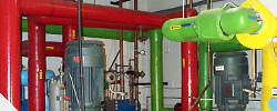 |
Facilities
The heat transfer loops allow applied and fundamental research on two-phase flows and boiling phenomena at high pressures and temperatures to be carried out. These loops can accommodate tubular or rod-bundle test sections of up to 3.5 m in length when installed vertically and 4.5 m in length when installed horizontally. Besides the test sections, the loops have auxiliary equipment used to maintain the temperature and the flow rate at the inlet, and the pressure at the outlet of the test sections constant during the experiments. The test sections are directly heated using a DC current and they are fully instrumented to measure detailed pressure drops, surface temperatures, mass flow rates and void fractions.
The interconnected subchannel test facility is used to conduct fundamental research on mass exchanges between subchannels under single- and two-phase flow conditions. The test section simulates two interconnected subchannels of a nuclear fuel bundle and it can be oriented vertically or horizontally. An air-water mixture is used to simulate steamwater flow at close to atmospheric pressure.
The counter-current flow rig has been designed to carry out experiments on two-phase counter-current flow. This facility can accommodate vertical test sections of up to 2.6 m in length and test sections consisting of vertical and horizontal runs in which the horizontal run may be up to 3.3 m in length. Both test sections are equipped with flanges to install orifices and study their influence on counter-current flows.
The flow pattern identification rig consists of a 2.4 m long square channel test section machined from a transparent acrylic bloc and the hydraulic equipment required to simulate two-phase flows. The test section is instrumented to measure signal fluctuations produced by axial void fraction gauges as well as local pressure transducers.
The air-water loop with QCV's is used to develop local and global void fraction gauges for vertical and horizontal two phase flows. The QCV system allows the average void fraction in the test section to be determined by weighing the trapped liquid (water) after suddenly closing the valves.